| 1.
Remove power from the unit. |
| 2.
Remove two screws from the top-front of
unit. Remove three screws form bottom-front of
unit. Gently remove the front cover panel.
Disconnect the connector to the front panel, if
necessary. |
| 3.
With an Allen wrench, loosen the set screw
holding the L.E.D. holder in place. The set screw
access is located on the back of unit. From
inside the cabinet, remove the L.E.D. and holder
by pulling it away from the light bench. |
| 4.
Unsolder or cut the two wires connecting the
L.E.D. to the main connector. Cut as close to the
L.E.D. holder as possible. Prepare the cut ends
for re-solder. |
| 5.
Note the replacement L.E.D. and holder has one
electrical connection longer than the other.
(Cathode) Solder the prepared black wire to the
shorter one and solder the remaining wire to the
longer one. (Anode) Isolate the electrical
connections so they will not touch during
installation or operation. |
| 6.
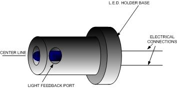
Insert the L.E.D. holder into the light bench.
Note the LIGHT FEEDBACK PORT in the holder. Make
sure it is pointed directly toward the front of
the unit in line with the photodiode also mounted
in the light bench. Press the L.E.D. holder into
the light bench up to the holder base and tighten
the set screw. |
| 7.
Connect the front panel connector. Connect the
power connector to the back of unit. While
viewing the cuvet, momentarily switch the main
power on and then off. You should see the L.E.D.
come on during that time. You should also see the
front panel light. If the L.E.D. did not come on,
recheck the connections and / or reverse the
electrical connections to the L.E.D. and re-test. |
| 8.
The L.E.D. current must now be set to
the proper range. Located close to the main front
panel connector are two test pins labeled LED 1
and LED 2. There is also a ten turn trim pot
labeled LED. Connect a volt meter to the two test
pins. Set the voltmeter range to read less than
one volt DC. Turn the power on and adjust the ten
turn trim pot until the voltmeter reads .200
volts or 200 mv. DO NOT leave the power on if the
reading is greater than .400 volts (400mv). If
the reading is greater than 400 mv, turn the
power off and turn the trim pot to it's lowest
level and restart the adjustment procedure. |
| 9.
Replace the front panel. Add water to clear the
cuvet. Set the mode selector to Cal, adjust for zero (0.00). As a further test you may also adjust the zero knob full clockwise to see a range of -0.020 to - 0.150 on the display ( with water in a clear cuvette ) in that range you will be able to adjust for zero. If by adjusting the zero knob clockwise you are unable to get at least -0.020, the 470nm (blue) filter will need to be replaced. They can be ordered from UDY Corporation or send the unit in for maintenance. |
| 10.
Your unit is now ready for operation. |